Construction of a new bascule bridge at Zollhafen Mainz
Starting position
The Zollhafen port area in the centre of the city of Mainz has been under construction since 2010. The 80,000 square metre harbour basin can be accessed via the harbour entrance which, until the Second World War, was spanned by a swing bridge. Since its destruction, there has been no connection between the north and south sides.
The Task
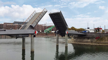
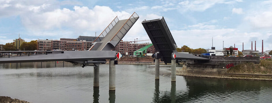
A central element of the local recreation concept for Mainz customs port is the Loop promenade that connects all the stations in the port. For this and to extend the existing waterfront promenade, a double bascule bridge for pedestrians and cyclists will be built on the old, listed bridge piers of the former swing bridge. The bridge consists of two fixed bridge sections and two moveable sections in the middle.
The 60 m long and 160 tonne bascule bridge connects the two sides of the bank at the harbour entrance. Because the water level can fluctuate up to 6 metres, a movable bridge was chosen so motor boats can still enter the harbour basin at high water levels. This also makes access by sailing boats possible.
For this project we performed both the electrical and mechanical engineering planning and the creation of the control software.
Services
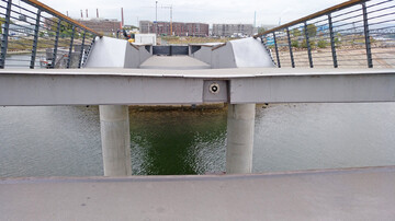
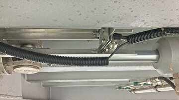
Two hydraulic cylinders per bridge, inclination sensors for position detection and limit switches for the operating and emergency end positions are used for the drive. The cylinders and the drive mechanism are visible to the user. In the closed position, the bridges are secured by a latch bolt as tip lock. This ensures that the two halves of the bridge are securely connected, even when the bridge has to bear a heavy load due to traffic, so no tripping hazards for pedestrians and cyclists arise.
We planned the power supply including the connection for an emergency power generator. Furthermore, the drives were designed to be redundant so the bridges can be operated at a reduced speed if a hydraulic cylinder or pump fails. The energy supply in normal operation is delivered from one side of the river with a 400 V three-phase current. The existing transformer station on the south pier was used, and a new one was built on the north pier.
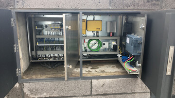
The switch cabinets, hydraulic power units and electrical equipment required were housed underground in the technical rooms (one each on the south and north pier). A hatch was fitted in the street to provide entrance to the technical rooms. The hatch is watertight to protect the technical equipment and prevent the underground spaces from flooding. A modular, powerful and fail-safe PLC is used to control the bridge. This allows for several operating modes (automatic, semi-automatic and maintenance mode), monitoring functions, the synchronisation of the sections during opening and closing and monitoring of the misalignment of the two cylinders for each section. The wind strength is also monitored in order to stop the bridge from opening in excessive wind speeds, which would potentially cause damage to the steel construction and mechanical engineering. The control software, including the user interface, was programmed by us.
Operation of the bridge incl. the sliding gates, traffic lights and navigation signals takes place in the on-site control point at the south pier. All functions can be controlled and faults displayed on a touch panel and through a radio transmitter. Remote control has also been prepared as an option. This includes a public address system for asking pedestrians and cyclists to leave the bridge. Acoustic warning signals to announce the movement of the motor-driven sliding gates, a navigation signalling system, an internal intercom system and lighting for the footpath and cycle path and for the danger zone around the sliding gates were also planned. Planning the earthing system, equipotential bonding and lightning and surge protection was part of our assignment, as well as the construction supervision and preparation of a risk assessment in accordance with the Machinery Directive.
Challenges and special features
The lighting for the bridge is integrated into the handrail on the railing. The bridge's folding function excludes the possibility of using continuous cables, so the power supply for the lighting runs from the bank side to the middle of the bridge. Trailing cables are used for cable routing over the pivot point to ensure that the bridges can also be illuminated when open.