Construction of the new Kattwyk railway bridge, electrical engineering planning
Starting position
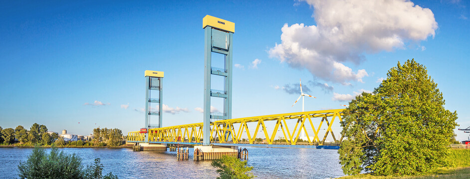
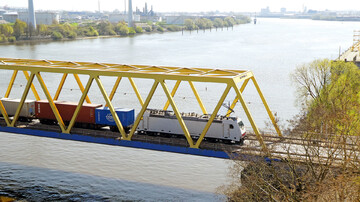
The existing Kattwyk bridge is a lift bridge over the Southern Elbe in the Port of Hamburg and connects the districts of Moorburg and Wilhelmsburg. The bridge is over 40 years old and is currently used by cars, trucks, pedestrians, cyclists and rail transport. If a train crosses the bridge it has to be closed to road traffic, which adds up to as much as seven hours a day. Owing to the increase in rail traffic in recent years, the bridge is showing signs of fatigue, which is leading to breakdowns. In addition, the bridge is raised every two hours during the day so that ships can pass. In order to optimise the flow of traffic in the south of Hamburg and minimise waiting times for car and truck drivers, a second lift bridge is being built. It is designed for double-track railway traffic as well as for cyclists and pedestrians. Road traffic continues to flow over the existing bridge. The new railway bridge will be built 58 metres north of the existing bridge and, at 133 metres wide, will have a much larger lifting section than the existing bridge.
The Task
The intention here is to improve the infrastructure in the Hamburg Port Southern Elbe area, curtail the waiting times for ships and vehicles and increase the flexibility of the railway. It should also be possible to control both bridges together after the new construction or modernisation. In order to meet these requirements, the modernisation of the electrical and control technology for the existing Kattwyk bridge was planned first and then the design of the electronic equipment for the new construction took place.
Services
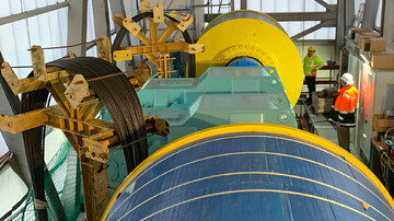
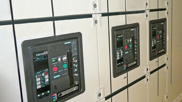
The scope of the planning included Installation Groups 4, 5 and 8 according to the Official Scale of Fees for Services by Architects and Engineers (HOAI) 2009, Sec. 53 Technical Equipment. The planning of the overall electrical equipment for the new construction of Kattwyk railway bridge and the modernisation of the existing bridge therefore included the instrumentation, control and communication technology. Following the completion of the new construction, the existing electronics for the existing bridge will be adapted to the state of the art and the current safety requirements. The output on the electrical drive power during normal operation of the existing Kattwyk railway bridge amounts to 2 x 132 kW and is therefore significantly lower than that of the new Kattwyk railway bridge (4 x 200 kW). This inequality is due to the different dimensions of the lifting section and the resulting difference in weight. An essential part of the task involved planning a joint control for the two bridges from one control station. The planning scope also included two medium-voltage switchgears and two low-voltage main distribution boards equipped with several low-voltage sub-distribution boards. The planning of the medium voltage feed, emergency power supply (emergency diesel 450 kVA and UPS) along with the earthing and lightning protection system for both bridges was also carried out. Technology controls are used for controlling the drives. A controller performs the other (administrative) control tasks in conjunction with numerous decentralised, independent controllers.
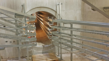
The new Kattwyk railway bridge is equipped with an underground culvert through which the signal, low and medium voltage cables for the railway and supply systems run in order to be able to control the bridge. The course of the accessible culvert runs between the two bridge pylons standing in the water at a depth of 35 metres under the Southern Elbe, is 124 metres long, consists of 61 concrete elements and has an internal diameter of two metres. From the one bank of the Southern Elbe, all the cables lead below the foreland bridge to the first pylon, run down within it, through the culvert, up again in the second pylon and below the foreland bridge to the opposite bank.
DriveCon was commissioned to plan the technical equipment for the culvert. In specific terms, our responsibility is for the cable support system and route planning. This means that we determined which cable has to be routed where in the culvert, to ensure that a cable spaghetti does not ensue at the end, and that all cables are laid properly and their bending radii are complied with. Only a 0.7 metre corridor is left in the middle once all the cables have been introduced. We have also planned the lighting and performed a lighting calculation to ensure that the required minimum lighting strength is achieved. We have also planned in emergency and safety lights to indicate where the exits are in the event of a power failure.
Challenges and special features
In order to minimise wear on the bridge, all the drive motors/axles for the respective bridge are also synchronised. Another special feature: the grid replacement power is used to open the bridges at a reduced speed in the event of a grid failure, thus ensuring ease of navigation for ships.